| Home | Energy | Nuclear | Electricity | Climate Change | Lighting Control | Contacts | Links |
|---|
INTRODUCTION:
This web page describes a module for growing uranyl nitrate hexahydrate [UO2(NO3)2.6H2O] crystals.
MATERIAL SELECTION:
The only
plastic that is HNO3 resistant is Teflon (PTFE).
The preferred materials are 440 stainless steel, ceramic, and
titanium. A counter current cascade of crystal growing modules is required
to achieve the desired separation.
The link https://www.rolledalloys.com/technical-resources/environments/nitric-acid/ indicates that various SS alloys are used in contact with 60% HNO3 at temperatures well in excess of 110 C. PTFE plastic could work, but is both structurally and thermally inferior to SS alloys, The heat conduction coefficient is also much lower than metals.
John Rudicile indicates:
We have to be aware that
the FP's contain halides which can make HNO3 far more corrosive. I
need to see the expected solution analysis of the product coming from
the fuel element dissolution step to account for the halide content.
I am aware than jacketed tanks are made of even carbon steel and
lined with teflon to make them near impervious to corrosion until the
eventual pin hole forms leading to liner failure and jacket
penetration. Heat transfer is impeded, but is still workable. Teflon
can be used over 200 C as long as it is not used in a structural
role. Similarly metal tubing can be teflon coated. For some services
polyvinyl difluoride (F analog of Saran) can be used in place of
teflon and it is somewhat more structurally robust.
Materials handling will be a dominant aspect of the design given the radio hazard content.
There is little incentive to try to save on equipment costs as
they will be at large variance with usual engineering economy of
scale cost calculations. The design must prioritize absolute
containment and separation completeness over almost all other
considerations. We want to do each step only once--no do overs at
least in a continuous flow mode.
UO2 2(NO3).6 H2O CRYSTAL GROWTH:
The crystal growth chamber is chosen to be a stainless steel 5 gallon (19 litre) pail with a teflon liner. The heat exchange elements inside this pail are 9 X 100 foot coils of (1 / 8) inch ID thin wall (.015 inch) teflon tube. Tefon has a very low stick surface. Hence crystal growth will preferentially occur on external seed crystals that rest on an exposed stainless steel fabric surface covering the pail bottom instead of on the teflon. Thus heat transport through the teflon should remain almost independent of the accumulation of crystals. During crystal growth mobile ions in solution bind to exposed seed crystal faces by giving up their binding energy, slightly heating the surrounding solution. The purpose of the teflon heat exchange coils is to remove that binding energy from the solution at a known rate. Hence control the temperature difference between the oil coolant circulated inside the teflon tubes and the solution temperature to control the crystal formtion rate. Note that the pail must be thermally well insulatated from its environment. Due to teflon tube bending radius of curvature constraints the teflon heat exchange tube bundles are close to the pail inside perimeter. The stainless steel seed crystal initiator mesh lies on small teflon balls that reat on the pail liner which rests on the pail floor, close to the pail axis. The agitation causes solution flow up throgh the mesh to constantly wash the crystal faces during crystal growth.
As the tefon heat exchanger cools the solution there is downward natural convection of the solution flow past the teflon tube coils. The cold end of each coil should be down. There is balancing natural convection upwards in the center of the teflon tube coils. This upward natural convection is asssisted by the central closd circuit pumped upward solution flow which provides controllable agitation for crystal face washing.
The object is to grow fewer large crystals rather than many smaller crystals so as to minimize the ratio of crystal surface area to crystal volume. The object is to have nearly continuous solution flow over the exposed crystal surfaces to continuously wash away impurities that will otherwise soon accumulate on the crystal faces if there is no solution flow.
It is contemplated that there should be a cylindrical teflon sheet divider between the teflon coils and the central crystal growth region to improve the natural convection solution flow pattern.
The agitation should be a closed circuit that draws solution uniformly from the top of the crystal growth chamber and injects it into the central teflon tube. This agitation mechanism may need a check valve so that it does not short circuit differential air pressure periodically used for tank to tank solution transfer.
Ideally the bottom of the crystal growth chanber should be conical to provide good liquid drainage away from the crystals. However, achieving this objective likely requires custom made pails.
CRYSTAL CHAMBER:
For proposed demonstration this chamber is a PTFE lined 19 litre stainless steel pail.
Consider use of a food grade stainless steel drum:
Inside diameter = 11.25 inch = 285.75 mm
Inside height = 11.75 inch = 298.45 mm
Inside volume = Pi (285.75 / 2)^2 (298.45) mm^3
= 19,139.648 mm^3
= 19,140 cm^3
= 19.140 lit
MINIMUM (1 / 8) INCH TEFLON TUBE BENDING RADIUS R CALCULATION:
Flexure Modulus = Y = 0.275 to 0.700 GPa
Tensile Strength = 13.0 to 55 MPa
Y = stress / strain = Pressure / fractional change in length
Length = 2 Pi R
Tube OD = 2 r
Fractional change in length = r / R
Pressure = Y (r / R)
or
R = Y r / pressure
For (1 / 8) inch ID tube:
r = 0.17 inch / 2
Minimum value of Y / pressure = 0.275 GPa / 55 MPa = 5
Maximum value of Y / P = 700 /13 = 53.8
Hence in the worst possible case the minimum value of R is:
R = 53.8 (0.17 inch / 2) = 4.6 inches
the actual inside turn radius is:
115 mm / (25.4 mm / inch) = 4.53 inch
The actual heat exchange tube radii are:
115 mm, 120 mm, 125 mm, 130 mm, 135 mm, 140 mm
The overall length of one layer is:
2 Pi [115 + 120 + 125 + 130 + 135 + 140] mm = 2 Pi [765 mm] = 4806.6 mm = 4.806 m
Each teflon tube makes 6 layers or:
6 X 4.806 m = 28.840 m
Each 100 foot tube is:
100 ft X 12 inch / foot X .0254 m / inch = 30.48 m
Thus with this coil configuration we have:
30.48 m - 28.84 m = 1.64 m
available for making coil end connections.
The central pail volume that contains no heat transfer coil is:
Pi (112 mm)^2 (298.45 mm)
= 11,761,359 mm^3
= 11.76 lit
The heat exchange tube solution displacing volume = 900 feet X 12 in / foot X 2.54 cm / inch X [Pi X ((.155 inch / 2) X 2.54 cm / inch)^2]
= 27,432 cm X 0.1217 cm^2
= 3339.5 cm^3
= 3.339 lit
Hence the solution volume is:
19.140 lit - 3.339 lit
= 15.801 lit
HEAT EXCHANGE COIL
The heat exchange coil is 9 X 100 feet of (1 / 8) inch ID teflon tubing with 0.015 inch wall. The effective heat transfer area of this tube is:
900 feet X 12 inches / foot X 2.54 cm / inch X Pi X 0.14 inch X 2.54 cm / inch = 30,646 cm^2
Thermal conductivity of teflon is: 0.45 X 10^-4 cal / s cm deg C
With a 10 deg C temperature difference in two hours this heat exchange coil will transmit:The minimum required heat = volume X 80 deg C
= 19 X 1000 gm X 80 deg C = 1,520,000 cal
Thus in principal the heat transport is sufficient for at least six cycles per day. However, we remain concernd about the crystal growth rate.
Need a custom machined stiff stainless steel lid for the pail that keeps the lid centered, that has a suitable perimeter rubber seal and that mounts the various connecting tubes.
The stainless steel lid must air seal to the pail rim. Both of these sealing surfaces must be flat.
The pail stainless steel lid needs 18 feed throughs for 9 heating/cooling loops, 12 feed throughs for agitation solution return flow, plus 7 feed throughs for:
a) Vent and liquid full sensor (teflon tube protrudes below stainless steel lid);
b) Warm fill;
c) Cool fill
d) Central common discharge and agitation supply
e) Solution temperature
f) Overfill alarm
g) Transfer air pressure
Note that the 12 feed throughs for agitation solution discharge must have teflon tubes that reach below the top surface of the liquid solution when the tank is full.
These holes are laid out in a hexagonal pattern with the common discharge amd agitation at the center, surround by six holes, surrounded by 12 holes for uniforn agitation flow, surrounded by 18 holes for the 9 X 100 foot lengths of teflon heat exchange tube.
The uranyl nitrate hexahydrate crystals are grown within the growth chamber.
May need a heavy steel split ring weight on top of the pail to balance the buoyancy force of the teflon tube coils. This force balancing inproves the lid's perimeter air seal.
INTERCONNECTING TUBING:
Recommend (1 / 8) inch ID tube connecting to (1 / 8) inch ????? male NPT fittings. The teflon tube must pass through the NPT section. Maximum tube OD = 0.130 inch + 2(.024 indh) = 0.130 + .048 = 0.178 inch = 4.5 mm
Each solenoid valve = $274.00 + HST
CRYSTAL GROWTH:
Crystal growth starts from a warm solution in tank Tnx in which the various species are fully dissolved. Hence U is in the (VI) oxidation state and there will be:
UO2++ ions
NO3- ions
H+ ions
OH- ions
H2O molecules
As heat is removed from the solution in tank T1a crystals will grow on the surface of the exposed stainless steel mesh.
If the solution is not agitated impurities will tend to concentrate on the crystal growth faces. To minimize the incorporation of these impurities into the crystals small continuous liquid agitation is required. This agitation is achieved by injecting a stream of solution into the bottom of the crystal growing tank. This agitation should also help keep the solution temperature uniform.
In order to achieve good impurity exclusion the rate of change of solution temperature during the crystal growth period must be limited to about 0.25 degrees C per minute.
The tanks should be thermally insulated from their environment so that the primary route for loss of heat is via heat conduction through the teflon tube coil.
When the solution has cooled to its lowest temperature it is necessary to drain off the remaining weak solution which will now have a higher concentration of impurities. The discharge tube drain inlet is at the very bottom center of each tank to try to expel all possible impurities. This weak solution flows into tank T1b. Then tank T1a is isolated and heated. After crystal melting strong solution is transferred into tank T2a.
Hence using a single two tank module to realize a consistent impurity concentration increase of a factor of two or an impurity concentration decrease by a factor of 10 by this method is relatively straight forward. Realizing an impurity concentration increase of a factor of ten or an impurity concentration decrease of a factor of 100 to 1000 requires use of a cascade with multiple stages.
This method of impurity concentration only works for impurities that are excluded during crystal formation. It does not work for Cs or Ba which chemically combine with the solid uranyl nitrate hexahydrate. We can improve the system performance by fitting the tank warm discharge with a micron filter so that filterable impurities are swept back into the tank by the agitation solution flow for subsequent discharge via the next cool solution discharge.
&nbp;
CRYSTAL GROWING APPARATUS DESCRIPTION (ONE OF 7 MODULES):
The crystal growing apparatus contains 9 vertical axis teflon tube coils within and concentric with a stainless steel cylindrical can.
The can is also closed at the bottom.
The teflon heat exchange tube is filled with a light low vapor pressure oil which serves as a heat transport fluid.
The space inside the can but outside the teflon heat exchange tube is occupied by uranyl nitrate hexahydrate solution and crystals. Crystals tend to grow on the upper textured surface of the bottom stainless steel mesh. The stainless steel mesh must provide good liquid drainage but must prevent the crystals from blocking the discharge tube.
The can has a heavy flat cap with a NC solenoid valve for liquid transfer gas pressure application. There are also two top ports for connecting liquid insertion tubes and there is a port for an air vent / overfill sensor.
There is a central thin teflon tube that is used for liquid discharge and for inserting recirculated agitation solution. This tube penetrates to the bottom of the tank and comes out the top going to three solenoid valves for warm liquid discharge, cold liquid discharge,agitation and a differential pressure sensor. The agitation has a flow rate adjustment. There is an immersed solution temperature sensor amd a common oil temperature sensor.
The vertical discharge tube has an additional side port for a liquid present differential pressure sensor.
I anticipate the likely necessity of making a series of crystal growth chamber prototypes to discover the best materials, dimensions, timing, etc. Once the module design is optimized it needs to be duplicated 7X.
Air pressure is used to transfer liquid solution between adjacent cascade tanks.
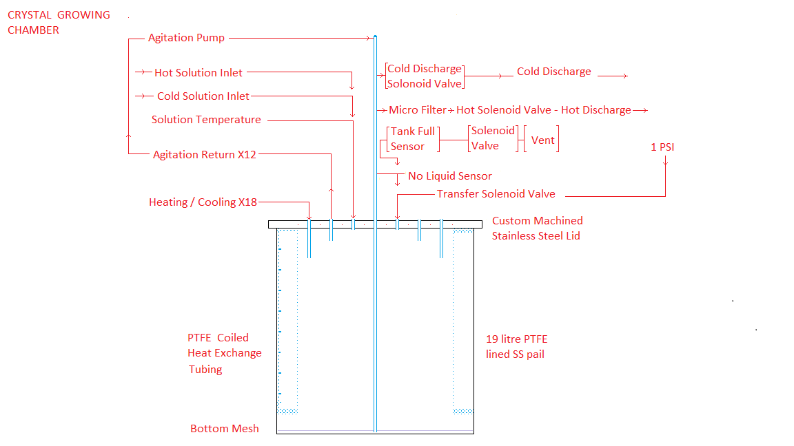
DIAGRAM OF CRYSTAL GROWTH CHAMBER
Each of the group a tanks has four dedicated PTFE solenoid valves, three of which are used for intertank liquid transfers and one which is used for agitation.
Each tank has two more binary outputs which are used for temperature control.
Each tank has a temperature sensor in the oil, a liquid present differential pressure sensor in the discharge tube and an overfill sensor on the air vent line.
STANDARD TANK MODULE HARDWARE:
The following list of hardware is potentially repeated 7X:
2 SS pails
2 pail liners
seed crystal start ring
Heavy Gravity tank lid with central hole for teflon feed tube, 1 hole for air pressure/vent solenoid valve, 2 holes for liquid insertion tubes, 1 hole for solution overflow sensor, teflon rim sealing ring
teflon heat exchange coils
low vapor pressure oil
2 Two foot diameter Cylindrical pail container with 6 inches of polystyrene insulation all around
Vertical teflon discharge tube
Liquid present detector in discharge tube tube
coarse Filter at bottom ofpail
Micro Filter assembly for warm discharge valve port
Shared air pressure source and pressure regulator for liquid transfer
One peristaltic pump and NC injection solenoid valve for agitation
2 Air flow adjustment cocks
Liquid temperature sensor at lowest point in pail
Two uranyl nitrate hexahydrate solution transfer teflon tubes from upstream modules
One NC tank top air pressure application / NO vent solenoid valve;
Two NC solenoid valves feeding solution to downstream modules
oil heating
oil cooling
Solution over fill sensor
Microcontroller
Differentialpressure sensor
STANDARD MICROCONTROLLER HARDWARE
Microcontroller
Four liquid transfer solenoid valve control binary outputs;
One NC air bubble solenoid valve control binary output for agitation;
Two binary outputs indicating to upstream controllers "ready for filling"
Two binary inputs sensing "ready for filling" from downstream controller
Binary input for overflow alarm
Binary input for liquid present sensor
Binary output to downstream module indicting liquid transfer complete;
Two binary outputs indicating program phase (hot, cooling, cold, warming)
Real time temperature display
Binary output for heating control
Binary output for cooling control
Program reset input
Binary output from overfill sensor
Binary input from local and upstream overfill sensors causing display warning LED, stopping of all air pressure application and agitation and opening of all vent valves
PROGRAM
Continuously cycles through four phases-hot, cooling, cold, warming
This web page last updated September 8, 2023
| Home | Energy | Nuclear | Electricity | Climate Change | Lighting Control | Contacts | Links |
|---|